In this guide, I'll cover how to build a dedicated video player built around a Raspberry Pi Zero – a small, low cost computer. The player uses arcade-style light up buttons to select a video and indicate what's currently playing.
This could be useful for museum displays, art or science projects, and other scenarios where visitors can choose from a selection of short videos. Some soldering is required to attach the buttons, but it's fairly basic.
The total cost is hard to pin down exactly – it depends whether buying in bulk, you already have certain adapters, etc. The total should come in under $40, excluding the 3D printed case. If paying just for 3D printing materials, the cost of the case should also be small.
Here's a video showing how the buttons work (scroll to the end for a photo of the player in a museum display):
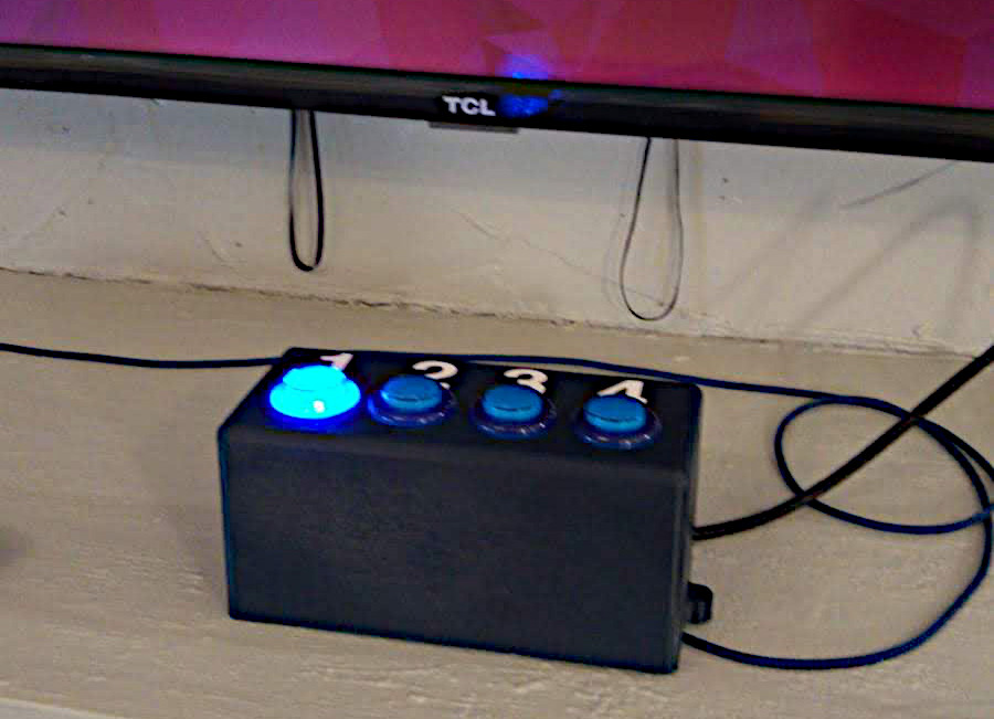
It's basically a 3D printed box containing a Raspberry Pi Zero W linked to four arcade-style light-up buttons. The button corresponding to the current video lights up.
The Raspberry Pi Zero W is a small, $10 computer running Linux. It's not very powerful, but it does have hardware accelerated video capabilities, so it can play HD 1080p video without a problem.
If you want to use 4K video, you'll need the more powerful Raspberry Pi 4, which sells for ~$35.
The rest of this guide covers the hardware. In part 2, I cover the software installation and configuration.
Parts list
I've listed parts and prices from Adafruit and Amazon US. For those in Europe, you might have luck finding these parts on your local Amazon site, https://shop.pimoroni.com/, or The Pi Hut.
- 3D printed case (see next section)
- Raspberry Pi Zero W ($10, Adafruit)
- Header pins ($0.95, Adafruit)
- Mounting screws (M2.5, 6mm) (A few cents from a hardware store, or part of a $6.92 kit on Amazon)
- 4x arcade buttons (30mm diameter) ($2.50 each, Adafruit)
- USB power adapter (5 Volt, 2 Amp) ($11.99 for a three pack from Amazon)
- Micro USB cable ($4.48, Amazon)
- Micro SD card ($5.49, Amazon)
- Connecting wires ($5.79 for 120pc kit, Amazon)
- Mini HDMI to HDMI adapter ($2.95, Amazon)
- HDMI cable ($6.99 for 6ft, Amazon)
- Spray paint (optional, a few dollars from hardware store like Home Depot)
For debugging and preparation:
- Micro USB-USB adapter ($2.50, Adafruit)
- USB keyboard
- HDMI monitor or TV
- Screwdrivers
- Soldering iron and solder
3D printed case
Here's a photo of the unpainted, freshly printed case:
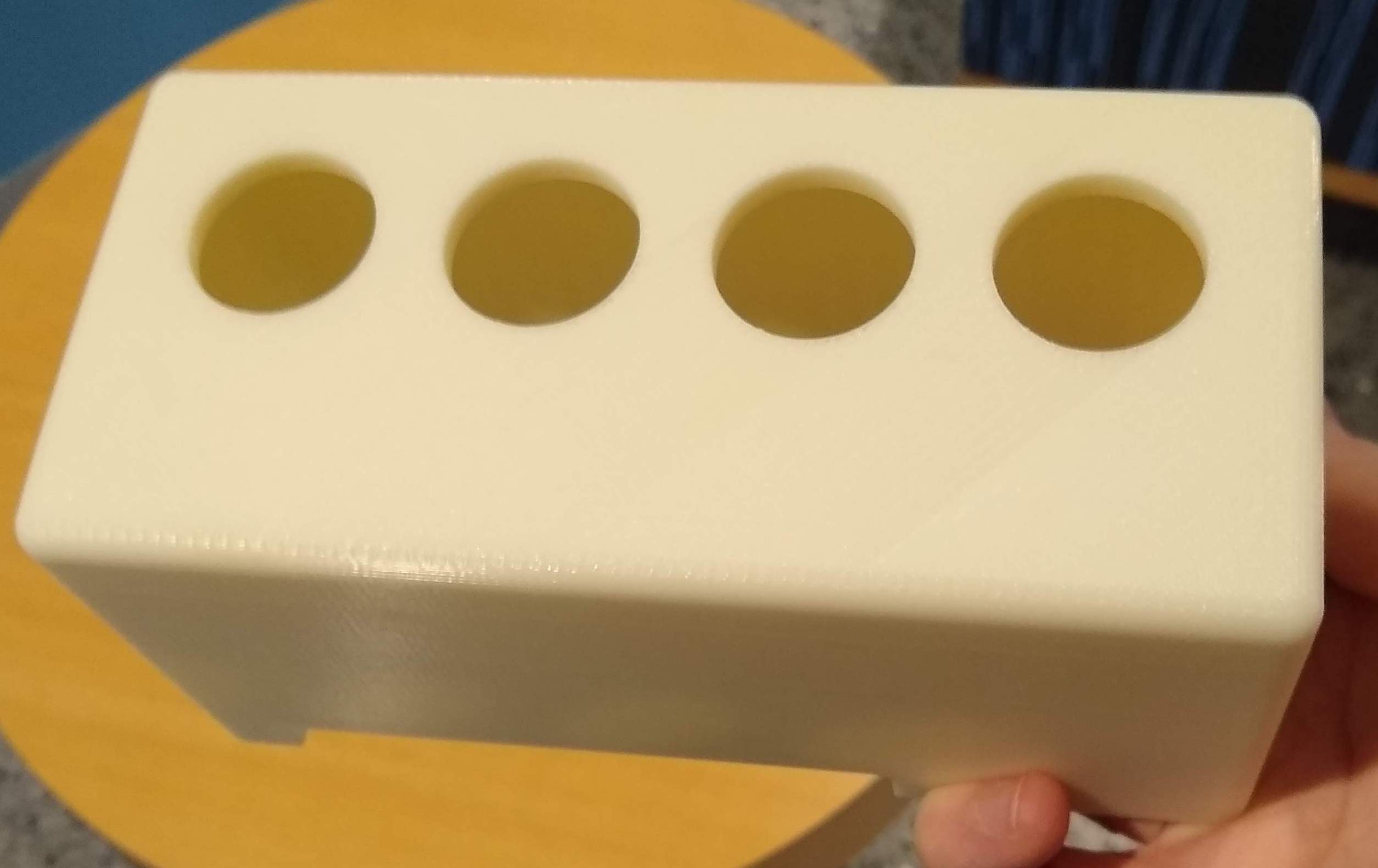
The design is just a bottomless box with four holes for buttons in the top, screw mounting holes for the Raspberry Pi, and a cutout at the back for cables connections while keeping the box flush to a surface.
I used Autodesk Fusion for the 3D design, which is free for personal use. One of the reasons I chose it was there's a nice absolute beginners video tutorial series on YouTube. Here's the CAD file for download:
This is actually my first attempt at making a 3D printed design, so it's not perfect. I thought about the cable connections, and the fact that HDMI cables often lack flexibility and will require a Mini HDMI to HDMI adapter. That part works well - but one difficulty is screwing in the Raspberry Pi, due to the angle of the board. A small screwdriver would work or, as I used, a flexible screwdriver extension.
Another downside is the case is quite deep. This is fine for vertical mounting (buttons on top, as we went for), but for wall mounting, a flatter design would be better.
Finally, you could just use a plastic project box, if you're happy to drill holes for the buttons etc. and prefer that to 3D printing.
Assembly instructions
Paint the case, if required
The case was 3D printed in white, so my first step was to spray paint it in "midnight blue". Any generic spray paint from a hardware store would probably do here - I used "Rust-Oleum Painter's Touch 2X Satin Midnight Blue General Purpose Spray Paint" (from Home Depot). If you're after a smooth finish, you might want to sand the box first before painting.
Attach header pins
"Header pins" are a set of pins which allow you to attach wires to the Raspberry Pi Zero W. Due to the board's low price, these pins don't come attached. Thankfully, there are several video tutorials on this already, such as the following:
The soldering is actually easier than it looks, it just requires a little patience as it has to be done pin-by-pin. Alternatively, Adafruit sell a "hammer header", which allows you to attach a set of header pins without any soldering.
Solder wires to buttons
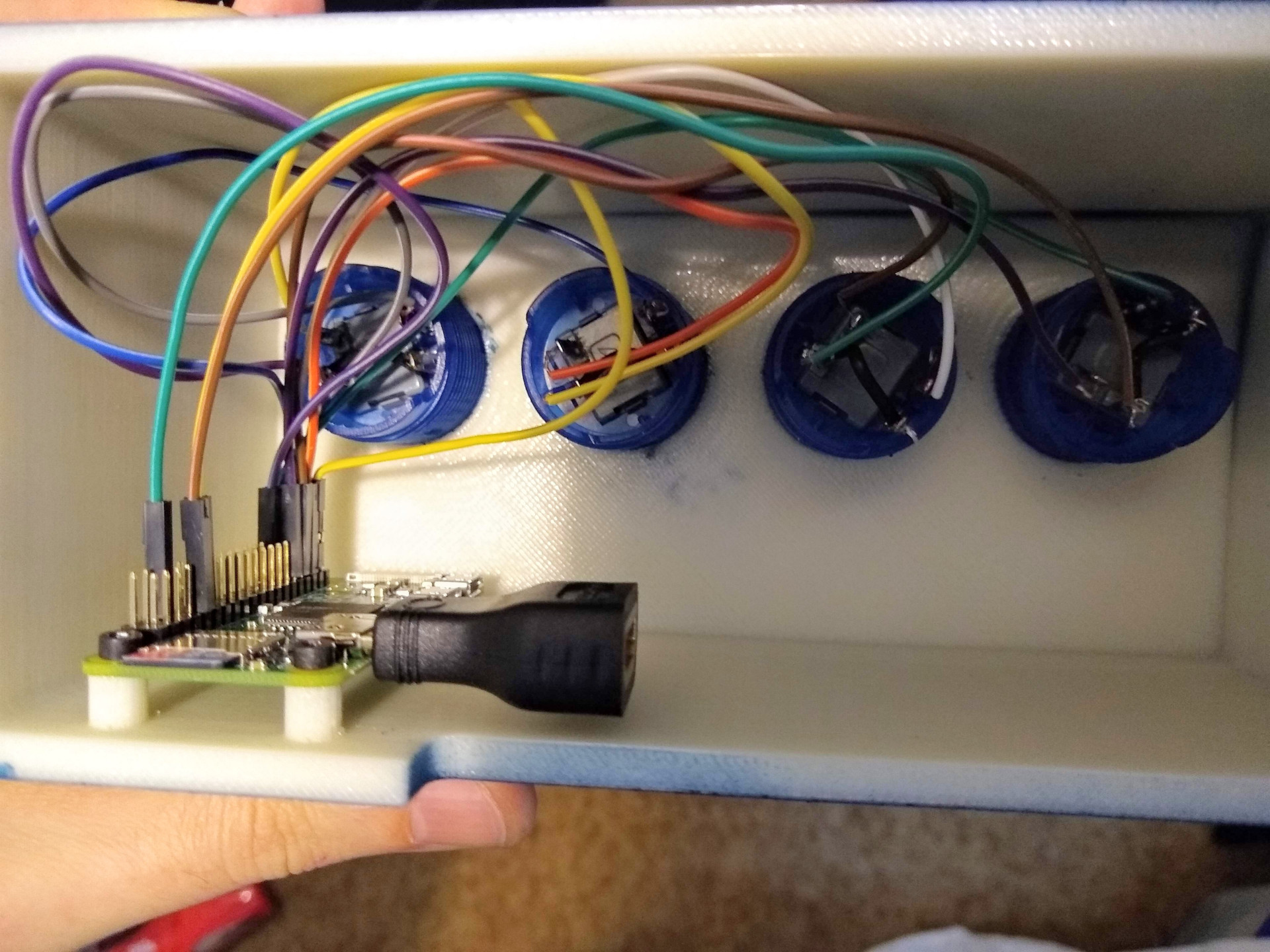
I used three wires for each button, each with bare wire on one end and a female "dupont" connector on the other. I created these wires by taking standard male (pin) to female (dupont) wires, and cutting off the "pin" ends.
I then soldered these wires to the LED positive and negative prongs, and one of the button prongs. Then, I soldered a short wire connecting the other button prong to the negative LED prong. That way, only one negative wire is required from the switch, for a total of three wires per switch rather than four going to the Raspberry Pi.
Mount the buttons and connect to the Pi
Next, insert one button at a time into the case, by pushing them down from the top. You may need to do a combination of pushing and twisting if it's a tight fit. Once in, the three wires need to be connected to the Rasbperry Pi. Here's a wiring diagram:
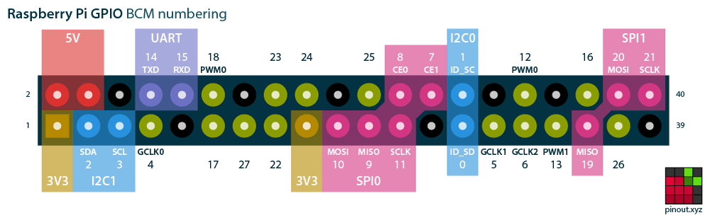 Image source: pinout.xyz
Connect the four negative/ground wires from the switches to any of the ground pins (shown in black). You could use any of the numbered "BCM" pins for the switch and LED connections, but I recommend pins 26, 19, 13, and 6 for the switches for buttons 1-4 respectively, and pins 21, 20, 16, and 12 for the LED positive pins for buttons 1-4 respectively. These are the defaults I use in my Raspberry Pi Video Player software, which I'll cover in part 2.
Screw down the Raspberry Pi
Next, screw down the Rasbperry Pi using four M2.5 6mm screws. You might need to use a flexible screwdriver adapter for this, since it's a tight fit, unless you have a short screwdriver handle available. Or, you could just attach only the bottom two screws - the Raspberry Pi is still held fairly securely.
The device is now finished! It just needs an operating system on the SD card and wiring up.
Prepare the microSD card
Download the Raspbian Lite image, which is the Linux operating system we'll be using. To write the downloaded image to the microSD card, you can use balenaEtcher. Full instructions are on the Raspberry Pi site.
Connect microSD, power, HDMI, keyboard
The remaining few steps are:
- Insert the micro SD card into the Raspberry Pi
- Connect the mini HDMI adapter to the HDMI cable
- Insert the mini HDMI adapter and cable into the Raspberry Pi, and connect the other end to a TV or monitor
- Connect the micro USB to USB adapter to the USB keyboard, and connect it to the Raspberry Pi micro USB port (NOT the one labeled "power")
- Connect a micro USB power cable to the micro USB port labeled "power", and connect it to mains power via a plug adapter
The final product
Here's the video player shown within the Jefferson Street Sound Museum in Nashville, Tennessee:
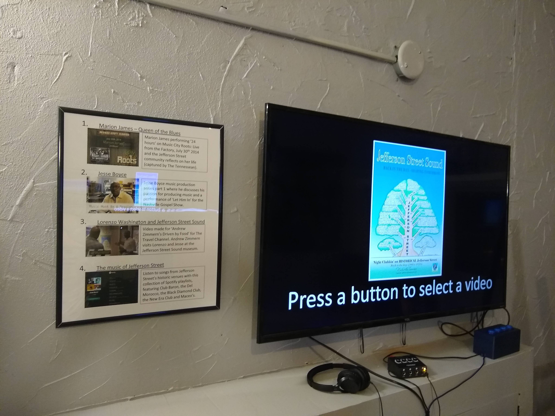
The video player is the box on the bottom right. On its left is a headphone amplifier, which (in addition to amplification) allows multiple sets of headphones to listen to the same video at once.
In part 2, I cover the software installation and configuration for the video player.
Thanks for reading!